Bearing preload is one of the most misunderstood tools in precision machinery — and one of the most powerful. Applied correctly, it turns a loose, slightly wobbly spindle into a rigid, repeatable, high-speed axis. Applied incorrectly, it generates heat, shortens bearing life, and can seize a spindle within hours. This guide explains what bearing preload is, the three methods used to create it, how DB, DF, and DT arrangements change rigidity, and the force rules that keep a preloaded pair safe at high speed. It is written for design engineers, maintenance technicians, and procurement professionals who need a practical, numbers-based answer rather than a vague recommendation.
What Is Bearing Preload?
Bearing preload is a permanent axial load applied to a bearing before the working load arrives, so that the rolling elements are always elastically compressed against the raceways. In engineering terms it is a deliberately manufactured “negative clearance” operating state: instead of leaving internal play in the bearing, preload removes it entirely and keeps every ball or roller in firm contact at all times.
Think of the difference this way: clearance gives a bearing room to move, while preload puts it under tension. A standard deep groove ball bearing with Normal clearance (CN) has a small amount of free axial play — the shaft can shift by a few micrometres before the balls take load. A preloaded angular contact pair has zero play: any force on the shaft, in either direction, is resisted from the very first micrometre. That is the entire point of preload — immediate stiffness and positional accuracy.
One boundary is worth stating early, because it causes endless ordering confusion: angular contact ball bearings and tapered roller bearings have no C2–C5 clearance groups. Angular contact bearings are set by preload class (light, medium, or heavy); tapered roller bearings are set by axial end play at assembly. Asking for “C3” on an angular contact bearing is meaningless — as explained in our bearing clearance guide, the C-groups only apply to deep groove ball, cylindrical, spherical, and needle roller bearings.
How Bearing Preload Is Applied: Three Methods
Axial preload is created in one of three ways, and the choice between them is often the difference between a stable spindle and a thermal runaway. Radial preload, used on cylindrical roller bearings, is a separate mechanism created by the interference fit itself and is covered in our bearing shaft fit tolerance guide.
1. Position preload
Position preload locks the two bearings at a fixed relative distance using spacers, shims, or a precisely machined housing. The preload force comes from the difference between the bearing widths and the spacer. This method gives the highest stiffness, because the whole bearing set acts as one rigid unit. Its weakness is temperature: as the shaft heats and expands, the inner rings squeeze together harder, so the actual preload grows with operating temperature — a positive feedback that must be accounted for in design.
2. Constant-pressure preload
Constant-pressure preload applies the axial force with springs — typically disc springs or coil springs — so the housing is free to move and the preload force stays fixed regardless of thermal expansion. Stiffness is slightly lower because the spring’s compliance is in series with the bearing set, but the preload is stable across the entire temperature range. This is the standard choice for high-speed and thermally demanding applications.
3. Adjustable preload
Adjustable preload uses a locknut and washer, ground spacers, a tapered seat, or hydraulic pressure to set the preload in the field. It is the classic method for tapered roller bearings and for spindles where the preload must be re-set during maintenance. The trade-off is that it depends on the fitter’s skill and a reliable measurement method.
| Method | Stiffness | Response to temperature rise | Best suited to |
|---|---|---|---|
| Position preload | Highest | Preload increases (thermal risk) | Stable-load precision spindles |
| Constant-pressure preload | Slightly lower | Preload stays constant (spring) | High speed, high temperature |
| Adjustable preload | Depends on method | Depends on method | Tapered roller bearings, field service |
The selection rule of thumb: need maximum rigidity with a stable thermal environment? Choose position preload. High speed or large temperature swings? Choose constant-pressure preload. Misapplying position preload to a hot application is the single most common cause of preload-related spindle failure.
Bearing Preload Arrangements: DB, DF, and DT
Angular contact ball bearings must be used in pairs to carry axial load in both directions, and the pair arrangement determines how much rigidity you get against tilting moments. Three arrangements cover virtually every application:
| Arrangement | Contact line direction | Load-center distance | Characteristic |
|---|---|---|---|
| DB (back-to-back, O-type) | Diverge outward | Large | Highest overturning-moment rigidity; standard for front spindle bearings |
| DF (face-to-face, X-type) | Converge inward | Small | Simpler assembly, tolerant of shaft deflection |
| DT (tandem) | Parallel, same direction | — | One-direction axial load only; builds capacity, creates no preload |
Contact angle suffixes are universal across manufacturers: C = 15°, AC = 25°, B = 40°. A larger contact angle increases axial load capacity but degrades high-speed performance, because the centrifugal effects discussed below grow more severe. High-speed spindles typically use 15° to 25°; heavy, low-speed positions use 40°. The bearing preload class you specify is always paired with one of these angle codes, so confirm both when ordering. Manufacturers document the same arrangement logic — see SKF’s bearing preload overview for the authoritative engineering treatment.
Why Bearing Preload Matters for Rigidity and High-Speed Accuracy
Rigidity: the nonlinear stiffness curve
Rolling bearings are strongly nonlinear springs. The axial deflection of a ball bearing follows δa ∝ Fa^(2/3) — which means the stiffness (dFa/dδa) grows with load and approaches zero at zero load. An unpreloaded bearing is therefore “soft” exactly where precision matters most: at light loads. Preload F0 moves the operating point up that curve, so the bearing starts at a meaningful stiffness instead of starting from nothing.
The chart below is computed for a 7205C angular contact pair (13 balls of 7.144 mm, 15° contact angle) with 100 N preload per bearing:
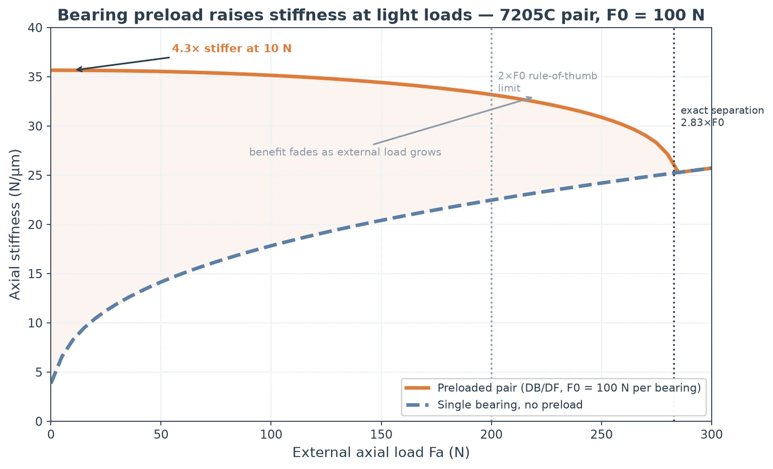
Three numbers matter here. First, the preloaded pair is 4.3× stiffer than a single bearing at 10 N external load, and 2.5× stiffer at 50 N — the benefit is largest exactly where spindles operate. Second, at zero external load the pair stiffness is 2× the single bearing’s stiffness at the preload point; that is the rigorous meaning of “preload doubles stiffness.” Third, the benefit fades as external load grows, which sets a hard selection rule described in the next section. At the other end of the spectrum, deep groove ball bearings such as the Talos 6201 ZZ are normally run with a positive clearance rather than preload; preload is a precision-axis tool, not a general-purpose upgrade.
Rotational accuracy
Preload eliminates the free axial play that shows up as shaft end float, so spindle positioning repeatability improves immediately. Because the balls are always in contact, the contact angles and load distribution stay stable, the rotation axis stays put, and runout — both radial and axial — benefits. For high-speed accuracy this matters even more: an unloaded ball at speed is free to wander, while a preloaded ball is held in a defined orbit.
Preventing skidding at high speed
At high speed with light load, the driving torque can be too small to keep the rolling elements rolling — they slide instead, producing the classic skidding/smearing damage pattern on the raceways and unstable cage motion. Preload guarantees a positive contact load at every rolling element, preserving pure rolling and protecting both accuracy and bearing life. This is the least visible but often the most valuable job of bearing preload in high-speed spindles, where manufacturers including Talos pair light preload with oil-air lubrication as standard practice.
How Much Bearing Preload: Force Rules and Selection
Two hard rules govern preload magnitude, and both are quantifiable.
Rule 1: stay between 1% and 10% of the dynamic load rating
Preload force F0 should generally sit between 1% and 3% of the bearing’s basic dynamic load rating C, with 10% as the absolute ceiling. Above that, the contact stress from preload destroys fatigue life — life scales roughly with the inverse cube of load — and heat generation becomes severe. For a 7205C (C ≈ 11.8 kN), the recommended band is 118–354 N; a light preload of 50–150 N sits comfortably inside it.
Rule 2: keep the external axial load below about 2× the preload
A preloaded pair splits an external axial load between its two bearings. As the load grows, the unloaded-side bearing gradually releases its preload, and the pair’s stiffness collapses when it detaches completely. For ball contact the exact separation point is 2.83× F0; the conservative engineering rule is to design so that the maximum axial working load (including shock) stays below 2 × F0. If the application’s axial load is 400 N, the preload per bearing must be above 200 N — choose the preload from the load, never from habit.
Setting preload by displacement
In practice, preload is set by displacement, not by force gauge: tighten the pair until a dial indicator reads the target closure, equal to twice the deflection δa(F0) of one bearing. For the 7205C the table below gives the closure for typical preload levels:
| Preload F0 (N) | Pair closure (μm) | Share of C |
|---|---|---|
| 50 | 10.6 | 0.4% |
| 100 | 16.8 | 0.8% |
| 200 | 26.7 | 1.7% |
| 300 | 35.0 | 2.5% |
| 500 | 49.2 | 4.2% |
Preload selection never happens in isolation. The shaft fit consumes radial clearance and adds its own contact load, and the temperature differential does the same — so preload, fit, and clearance must be designed together, not independently. Our shaft fit tolerance guide and bearing clearance guide cover the other two legs of that calculation in depth.
Bearing Preload at High Speed: Centrifugal Force and Heat
High speed changes the preload game completely, because of centrifugal force on the balls. Each ball experiences Fc = m·ω²·Dm/2 — and the numbers are startling. For the same 7205C, the centrifugal force per ball reaches about 127 N at 20,000 rpm and 285 N at 30,000 rpm:
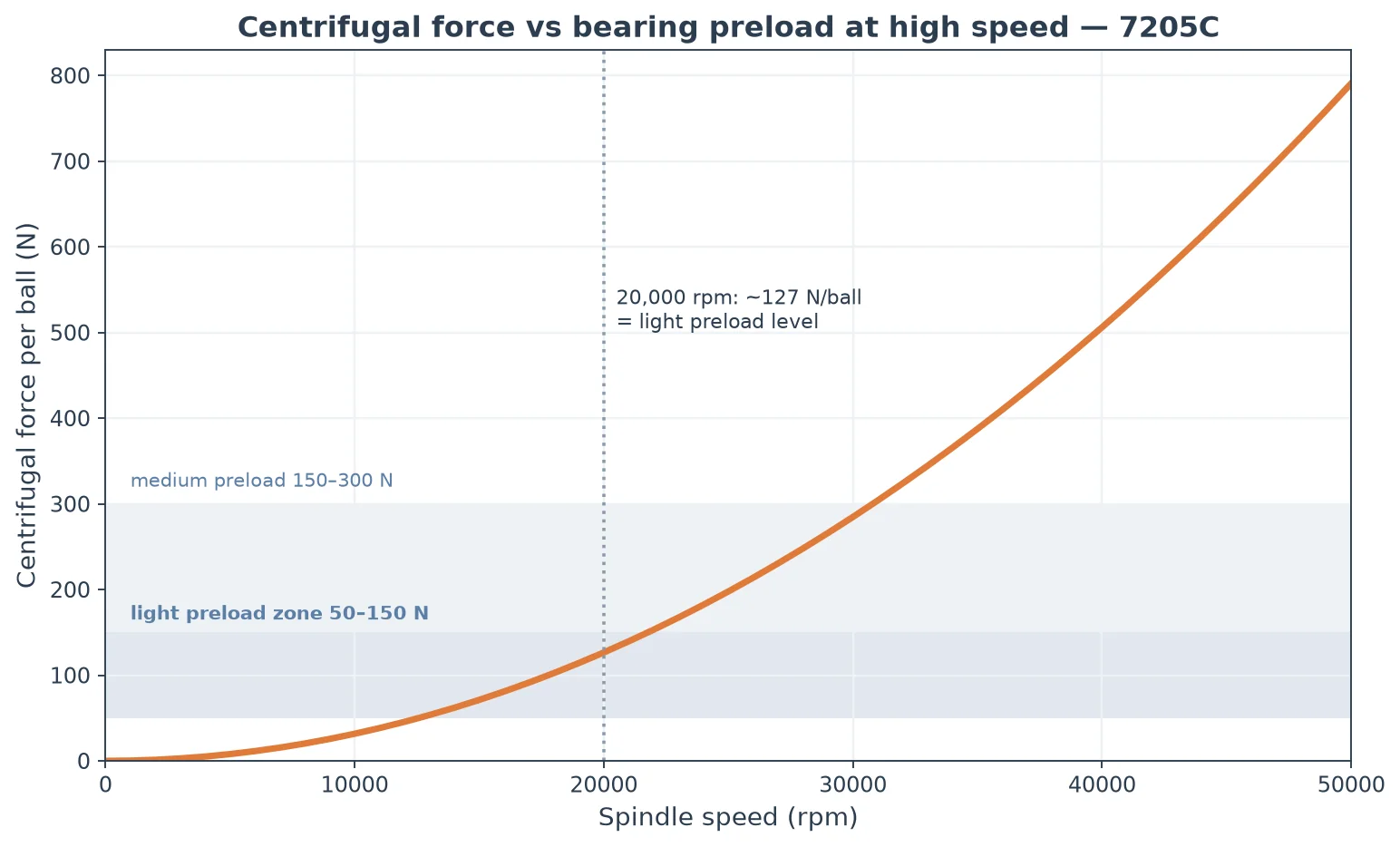
At 20,000 rpm the centrifugal force per ball is already at the level of a light preload; at 30,000 rpm it is several times larger. The consequences are serious:
- The balls are pressed hard against the outer raceway, so the outer-ring contact load rises while the inner-ring contact load drops — the effective preload state drifts with speed instead of staying where it was set.
- Higher contact load means more friction heat; in a position-preloaded set, the hot inner ring expands and squeezes the pair harder, raising the preload further — a positive feedback that can end in thermal seizure.
- The fix is a lighter preload grade plus oil-air or oil-mist lubrication for high dn values, and constant-pressure (spring) preload or a manufacturer high-speed design where the speed is very high. Bearing dimensions and precision grades follow ISO 492; preload practice does not — it is an application engineering decision, which is exactly why the preload class must be specified deliberately rather than copied from a parts list.
Common Bearing Preload Misconceptions
Misconception 1: “More preload is always stiffer”
Wrong. Above the needed level, extra preload adds heat and cuts fatigue life by roughly the inverse cube of the load increase, and at high speed it can trigger thermal runaway. The correct principle is the lightest preload that meets the stiffness target.
Misconception 2: “Position preload works in hot applications”
Position preload amplifies with temperature — the classic thermal runaway. Hot, high-speed applications need constant-pressure preload so the force stays fixed.
Misconception 3: “I can preload a cylindrical roller bearing axially”
Never. NU/NJ cylindrical roller bearings have no axial locating feature; axial preload makes the rollers skew and smears their end faces. They are radially preloaded only, through the interference fit itself.
Misconception 4: “Angular contact bearings need C3 clearance”
Angular contact bearings have no C-groups — they are set by preload class. Tapered roller bearings are set by axial end play. Ordering “C3” on either type just confuses the supplier.
Misconception 5: “Preload is independent of fit and clearance”
The three interact: an interference fit consumes clearance and adds contact load, temperature consumes clearance, and preload adds more. On a precision pair they must be stacked and checked together — which is why the preload class, the shaft fit, and the clearance group belong on the same engineering sheet.
Frequently Asked Questions
What is bearing preload?
Bearing preload is a permanent axial load applied to a bearing before working load, so rolling elements stay elastically compressed against the raceways. It removes internal play, giving immediate stiffness, better rotational accuracy, and protection against skidding at high speed.
What is the difference between position preload and constant-pressure preload?
Position preload locks the bearing pair at a fixed distance with spacers, giving the highest stiffness but causing the preload to grow with temperature. Constant-pressure preload uses springs so the force stays fixed across the temperature range, at the cost of slightly lower stiffness. Use position preload for stable thermal environments and constant-pressure preload for high-speed or hot applications.
What is the difference between DB, DF, and DT bearing arrangements?
DB (back-to-back) has contact lines diverging outward and the largest load-center distance, giving the highest rigidity against overturning moments — the standard front-spindle choice. DF (face-to-face) converges the contact lines for simpler assembly. DT (tandem) mounts the bearings in the same direction and handles one-direction axial load only, with no preload created.
How much preload should I apply?
Stay between 1% and 10% of the bearing’s dynamic load rating C (1–3% is the recommended band), and keep the maximum axial working load below about 2× the preload force per bearing. Then set the preload by displacement: tighten the pair to a closure of twice the single-bearing deflection at the target preload.
Why do high-speed spindles use light preload?
At high speed, centrifugal force presses the balls against the outer raceway with forces comparable to a light preload — about 127 N per ball at 20,000 rpm on a 7205C. Heavier preloads add heat on top of this, raising the risk of thermal seizure. Light preload plus oil-air lubrication is the proven high-dn combination.
Is a preloaded Talos bearing equivalent to a preloaded SKF or NSK bearing?
Yes, in the sense that matters. The bearing itself is manufactured to the same ISO 492 tolerance classes as SKF, NSK, and FAG equivalents, so a Talos angular contact pair accepts the same preload class and produces the same stiffness response. Preload values, however, are defined by each manufacturer’s grade table (light/medium/heavy differ slightly between brands), so confirm the exact force or displacement against the catalog when cross-referencing.
Conclusion
Bearing preload is the tool that turns an ordinary bearing pair into a precision axis: it delivers 2–4× stiffness at light loads, removes free play for accuracy, and prevents skidding at speed — provided the preload is sized by the rules. Keep the force between 1% and 10% of C, keep external axial load below 2× the preload, choose position preload only where temperatures are stable, and step down to light preload with oil-air lubrication as speed rises. Where clearance is the tool for everyday machinery, bearing preload is the tool for spindles that must be both rigid and accurate at high speed.
Need angular contact bearings for a preloaded spindle or precision pair? Browse our angular contact ball bearings or contact our engineering team for a preload recommendation matched to your load, speed, and temperature conditions — including the displacement values you need to set the preload correctly on the assembly line.