A bearing clearance test performed after mounting is the only reliable way to confirm that an interference fit has not consumed the internal play your application needs. Every press-fit or shrink-fit installation removes clearance — roughly 60–80% of the interference value on a solid shaft — and if too much disappears, the bearing overheats, vibrates, and can seize within days of commissioning. This guide explains four practical bearing clearance test methods — the lead wire method, the feeler gauge check, the dial gauge shaft lift test, and displacement sensor measurement — and shows how to judge the result against the residual clearance your bearing should retain after mounting.
The methods range from a five-minute field check on a large roller bearing to micrometre-resolution sensor rigs on critical machines. None of them requires removing the bearing from its shaft, and all four verify the same physical quantity: the radial clearance left between the rolling elements and the raceways once the fit has done its work.
What Is a Bearing Clearance Test?
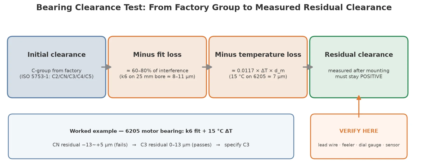
A bearing clearance test measures residual clearance — the internal radial play that remains after the bearing has been mounted but before it runs under load. The factory clearance group printed on the box (C2, CN, C3, C4, or C5, defined by ISO 5753-1) is measured on an unmounted bearing under a standardized measuring load. Mounting changes that number: an interference fit stretches the inner ring outward and consumes clearance, and in service the hotter inner ring expands and consumes more.
Residual clearance follows a simple chain:
Residual clearance = initial clearance group − interference fit loss − temperature differential loss
Fit loss is roughly 60–80% of the average interference — a 6205 bearing on a k6 shaft loses about 8–11 μm at assembly. Temperature loss is about 0.0117 × ΔT (°C) × mean diameter (mm), or roughly 7 μm for the same 6205 with a 15 °C inner-to-outer ring differential. The clearance groups themselves are explained in our bearing clearance guide, and the interference-fit side of the equation is covered in our bearing shaft fit tolerance guide — clearance and fit belong on the same engineering sheet, never as separate specifications.
That is why the post-mounting bearing clearance test exists: the calculation predicts, but only a measurement confirms. Actual interference depends on the real shaft diameter, the surface finish (rough surfaces silently cancel several micrometres of effective interference), the housing wall thickness, and whether the ring seated fully — none of which a drawing can guarantee. The factory measured the clearance it shipped; the bearing clearance test re-measures it in the condition that actually matters. The group ladder follows ISO 5753-1 in both cases, so a measured value can be compared with published ranges as long as the measurement conditions are equivalent.
How to Run a Bearing Clearance Test: Four Field Methods
Four methods cover every practical situation, from a quick check on a split-housing bearing to permanent online monitoring. The right choice depends on bearing type, size, and how much access the machine allows:
| Method | What it measures | Best suited to | Typical accuracy |
|---|---|---|---|
| Lead wire | Squeezed wire imprint between roller and outer raceway | Cylindrical and spherical roller bearings | ±5–15 μm |
| Feeler gauge | Blade thickness in the top (unloaded) gap | Large roller bearings in split housings | ±10–50 μm |
| Dial gauge (shaft lift) | Jacked shaft travel relative to the housing | Any mounted bearing — the field default | ±10–30 μm |
| Displacement sensor | LVDT or eddy-current probe displacement | Precision work, online monitoring, trending | ±2–10 μm |
Method 1: The Lead Wire Clearance Test
The lead wire method is the classic bearing clearance test for roller bearings. A soft annealed lead wire (or a plastic imprinting wire) is laid along the roller axis between a roller and the outer raceway in the loaded zone, the rings are rocked under a steady radial load so the roller squeezes the wire flat, and the imprint thickness is measured with a 0.01 mm micrometer. The compressed thickness equals the gap at that point — the residual clearance in the loaded zone.
Place two or three wires 120° apart, use a wire diameter at least three to five times the expected clearance, and average the readings from several cross-sections of each imprint. The result is direct, inexpensive, and usually accurate to ±5–15 μm. Its limitation is applicability: the method suits line-contact cylindrical and spherical roller bearings, where the imprint is uniform. On ball bearings the ball leaves a local indentation instead of a flat imprint, so the reading is unreliable. The bearing raceway must be accessible, which usually means removing a housing cover — but never the shaft.
Method 2: The Feeler Gauge Clearance Check
The feeler gauge check is the fastest bearing clearance test available. On a horizontal shaft the roller set settles to the bottom of the outer ring, so the gap at the top — the unloaded zone — is the largest, and a calibrated feeler blade inserted there gives a direct reading of the radial clearance. On a split housing, remove the cover, insert blades from thin to thick at the top between the top roller and the outer raceway, and take the thickest blade that slides in with a slight drag.
This method needs only a feeler set and a few minutes, which makes it the standard first-line check for large roller bearings (typically above 200 mm outside diameter, where the gap is large enough to admit a blade). Accuracy is the coarsest of the four — ±10–50 μm, depending on blade steps and feel — and clearances below about 30 μm cannot be measured this way at all. Keep the blade perpendicular to the roller axis, keep surfaces clean, and treat the reading as a verification rather than a precision measurement.
Method 3: The Dial Gauge Shaft Lift Test
The dial gauge shaft lift test is the workhorse bearing clearance test for mounted bearings of every type. A dial indicator (0.001 mm resolution) is clamped to the bearing housing — never to the shaft — with its plunger resting vertically on the shaft, then a hydraulic jack or pry bar lifts the shaft under the bearing until the rollers or balls contact the outer raceway and the indicator stops moving. The travel read on the dial is the residual clearance at that angular position.
Apply the lifting force slowly and keep going until the reading plateaus; a partial lift stops in the elastic zone and reads low. Repeat two or three times and average, confirm the dial returns to zero after each release, and on long rotors mount a second indicator on the far side or correct for shaft deflection. Accuracy is typically ±10–30 μm in the field — ample for large bearings whose residual clearance is measured in tens of micrometres. This is the same rocking-displacement principle used by the ISO 5753-1 factory measurement, adapted to a mounted bearing — see the SKF bearing mounting guidelines — and it is the method most overhaul specifications cite for acceptance.
Method 4: The Displacement Sensor Clearance Test
The displacement sensor method replaces the dial gauge with an LVDT (contact) or eddy-current (non-contact) probe for the highest precision and for continuous monitoring. On a bench or in a machine, a probe measures shaft-to-housing travel while a load is applied; two probes mounted radially opposite each other are summed to cancel structural deflection, and a data logger records the force–displacement curve automatically. Resolution reaches 0.1–1 μm, with system accuracy of ±2–10 μm.
Non-contact eddy-current probes have a second, increasingly common role: permanent online bearing clearance monitoring on large rotating machinery — turbines, generators, large pumps, wind turbine main bearings. The probes track shaft position continuously, so a clearance that is shrinking (thermal runaway before seizure) or growing (wear or inner-ring creep) shows up as a trend before it becomes a failure. The cost is the highest of the four methods, and the probes need mounting holes and calibration, but for critical machines the continuous record is often worth the investment.
What Your Bearing Clearance Test Result Should Be
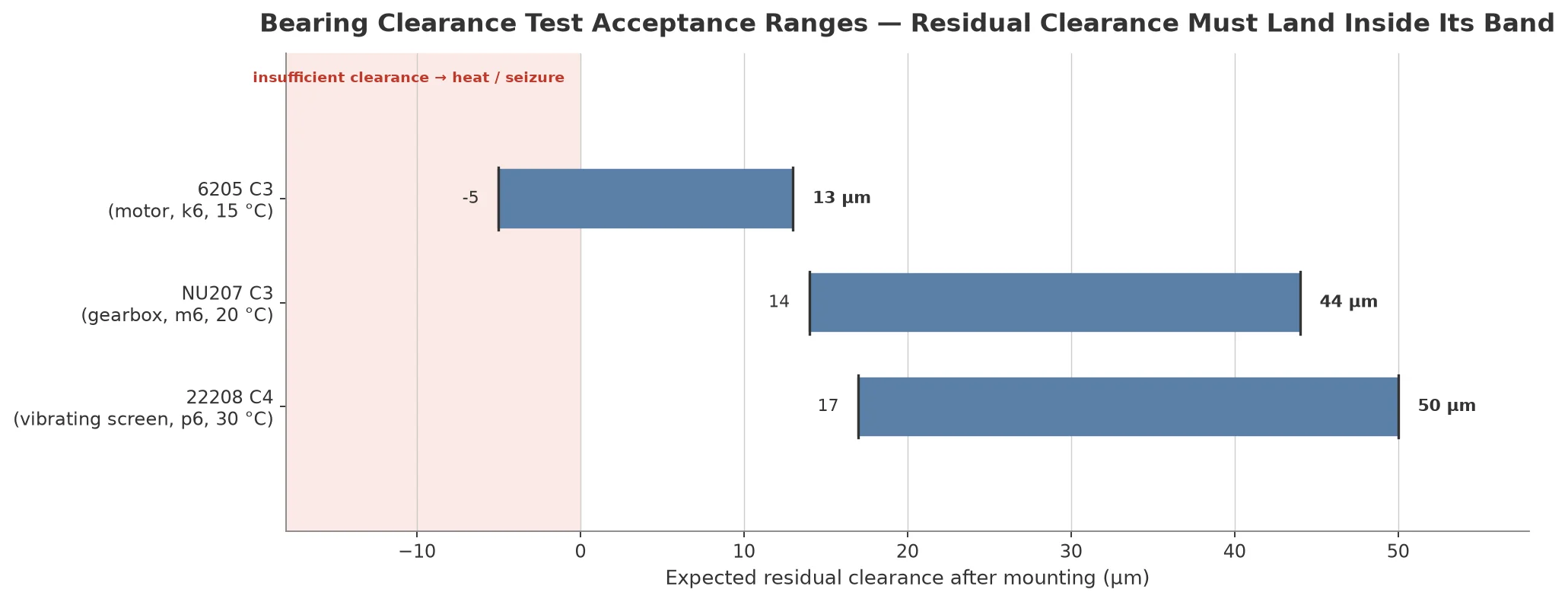
Two rules decide whether a bearing clearance test reading is acceptable. First, the residual clearance must be positive: a negative value after mounting is a fault condition, not a borderline case. Second, the reading should fall inside the expected residual range for the bearing, its fit, and its duty — the initial group minus the two losses. The chart below shows the expected ranges for three typical installations, computed from ISO 5753-1 group values with verified fit and temperature losses:
| Bearing | Duty and fit | Expected residual clearance |
|---|---|---|
| 6205 C3 | Electric motor, k6 shaft, 15 °C ΔT | 0–13 μm (typical; worst case −5 to +13) |
| NU207 C3 | Gearbox, m6 shaft, 20 °C ΔT | +14 to +44 μm |
| 22208 C4 | Vibrating screen, p6 shaft, 30 °C ΔT | +17 to +50 μm |
A reading below the expected range points to a fit problem: interference heavier than specified, a rough shaft surface eating effective interference, a shoulder fillet blocking the ring, or a ring that did not seat fully. A reading above the range points the other way — a looser fit than intended (a future creep risk) or an out-of-spec clearance group in the incoming bearing. Two practical corrections apply before judging: measure cold (a hot bearing reads low, because thermal expansion has already consumed clearance — correct by the 0.0117 × ΔT × d_m rule), and take at least three readings at the same angular position, because a single reading can be fooled by seating, debris, or a loose gauge base. The manufacturers’ manuals describe the same acceptance logic — see SKF’s guidance on selecting internal clearance.
If the expected residual range for a new design is near zero or negative, the clearance group is wrong, not the measurement: specify C3 where CN is consumed by the fit, C4 where C3 is consumed by fit plus heat. This is why electric motor bearings are C3 as standard and heavy hot-duty positions run C4. Talos supplies every ISO 5753-1 group and states the measured clearance range on the inspection report, so the acceptance target for a post-mounting bearing clearance test is always a published number rather than a guess.
Common Bearing Clearance Test Mistakes
Most field errors do not come from choosing the wrong method — they come from executing it incorrectly. The six mistakes below produce readings that are confidently wrong:
- Angling the feeler blade — a blade inserted diagonally catches the roller chamfer and reads high. Keep it perpendicular to the roller axis and clean the gap first; oil and grit make blades stick and report phantom clearance.
- Clamping the dial gauge to the shaft — the indicator must sit on the housing or a fixed structure. Mounted on the shaft it moves with the shaft and reads zero regardless of the actual clearance.
- Lifting with too little force — a partial shaft lift stops in the elastic contact zone and reads low. Increase the jack force until the dial plateaus; only a plateau is a valid reading.
- Placing lead wire in the unloaded zone — the wire must sit between a loaded roller and the raceway. In the unloaded zone the gap is not fully closed under the squeeze, and the imprint reads high.
- Testing a hot bearing — a bearing that has just run reads low because heat has already consumed clearance. Cool it to ambient, or correct with the temperature-loss formula, before comparing against the acceptance range.
- Comparing a field reading directly to the factory C-group table — the factory table describes an unmounted bearing under a standardized measuring load. A field reading must be compared to the expected residual range (group minus fit and temperature losses), not to the raw group values.
One more boundary is worth stating, because it causes endless confusion: angular contact ball bearings and tapered roller bearings have no C2–C5 clearance groups at all — they are set by preload class and axial end play respectively, as our bearing preload guide explains. Radial bearing clearance test logic simply does not apply to them; their acceptance check measures axial end play instead. And when a measured value does land in range, the group itself is fully comparable across brands — ISO 5753-1 defines the same values for every manufacturer, so a Talos C3 bearing and an SKF or NSK C3 bearing of the same size are effectively equivalent, and the same acceptance range applies to both. The one exception to watch is sealed or shielded bearings, where some manufacturers apply a slightly reduced clearance table; confirm the value in the catalog before judging the measurement.
Frequently Asked Questions
What is a bearing clearance test?
A bearing clearance test measures the residual radial clearance that remains after a bearing has been mounted — the initial clearance group from the factory minus the interference fit loss and the temperature differential loss. It verifies that the fit did not consume so much clearance that the bearing will overheat, vibrate, or seize in service.
How do you measure bearing clearance after mounting?
Four practical methods are used: the lead wire method (squeeze a soft wire between a roller and the raceway and measure the imprint), the feeler gauge check (insert calibrated blades into the top gap of a large roller bearing), the dial gauge shaft lift test (jack the shaft and read the travel with a dial indicator), and displacement sensors (LVDT or eddy-current probes for precision and online monitoring).
Which bearing clearance test method is most accurate?
Displacement sensors are the most accurate at ±2–10 μm system accuracy, followed by the lead wire method at ±5–15 μm, the dial gauge shaft lift test at ±10–30 μm, and the feeler gauge check at ±10–50 μm. Accuracy trades off against speed and cost — choose the method that matches the bearing size, the access you have, and the accuracy the acceptance procedure requires.
Can I check bearing clearance without removing the bearing?
Yes. The dial gauge shaft lift test works on a fully mounted bearing and is the standard in-situ acceptance check. On large roller bearings in split housings, removing the housing cover allows a feeler gauge check without touching the shaft. The lead wire method also works in place on open roller bearings, requiring access to the raceway rather than shaft removal.
What happens if residual clearance is too small?
Insufficient clearance means the rolling elements are jammed between the raceways: the bearing runs hot, vibrates, and in the worst case seizes — a failure often misdiagnosed as a lubrication problem. If the bearing clearance test shows near-zero or negative residual clearance, step up to the next clearance group (C3, or C4 for heavy fits plus heat) or reduce the interference fit.
Is a Talos C3 bearing the same as an SKF or NSK C3 bearing?
Yes — the clearance values are defined by ISO 5753-1, so a Talos 6205 C3 and an SKF or NSK 6205 C3 carry the same 13–28 μm range and are effectively equivalent. The same acceptance range applies to both in a post-mounting bearing clearance test. Talos deep groove ball bearings ship with C0 (Normal) as standard and are available in C2, C3, C4, and C5, with the measured range stated on the inspection report.
Conclusion
A bearing clearance test after mounting turns a clearance calculation into a verified fact. Lead wire, feeler gauge, dial gauge, and displacement sensor methods cover everything from a quick check on a large roller bearing to continuous monitoring on a critical machine, and the acceptance rule is the same for all four: the residual clearance must stay positive and inside the expected range for the fit and duty. Measure cold, take repeat readings, and compare against the residual range — not the raw factory table. For the mounting practice that protects the clearance you specified, see our bearing mounting techniques guide, and for the group selection behind the numbers, the bearing clearance guide is the natural companion read.
Need deep groove ball bearings in the clearance group your application requires — with the measured range documented? Browse our deep groove ball bearings, including the Talos 6201 ZZ, or contact our engineering team for a clearance and fit recommendation matched to your load and temperature conditions.