Every maintenance engineer who has pressed a bearing onto a shaft has asked the same question: how much force do I actually need? A press fit force calculation answers that question with numbers instead of guesswork, and it is also the best protection you have against damaging the cage or the raceways. This guide explains the four-step press fit force calculation, works a real example on a 6205 bearing, and shows why the mounting force must always be applied to the ring with the interference fit. The same physics applies whether you are mounting a small 6202 deep groove ball bearing or a heavy 22208 spherical roller bearing.
What Is a Press Fit Force Calculation?
Press fitting means pushing a bearing over a shaft (or into a housing) whose dimensions deliberately overlap the bearing bore. That overlap is called interference. The force needed to slide the two parts together is simply the friction between them: the tighter the fit, the higher the contact pressure, and the more tonnage the press must deliver.
A press fit force calculation quantifies that friction before you touch the press. It is built on two well-established engineering models: the Lamé thick-cylinder equation, which converts interference into contact pressure, and Coulomb friction, which converts pressure over the contact area into force. The result is a number you can compare with your press’s load cell — and a number that tells you whether the mounting procedure is safe for the bearing itself.
If the fit class has not been selected yet, the bearing shaft fit tolerance guide covers k6, m6, n6 and p6 selection in detail, including the load-direction rule and clearance-loss effects.
How to Perform a Press Fit Force Calculation (Step by Step)
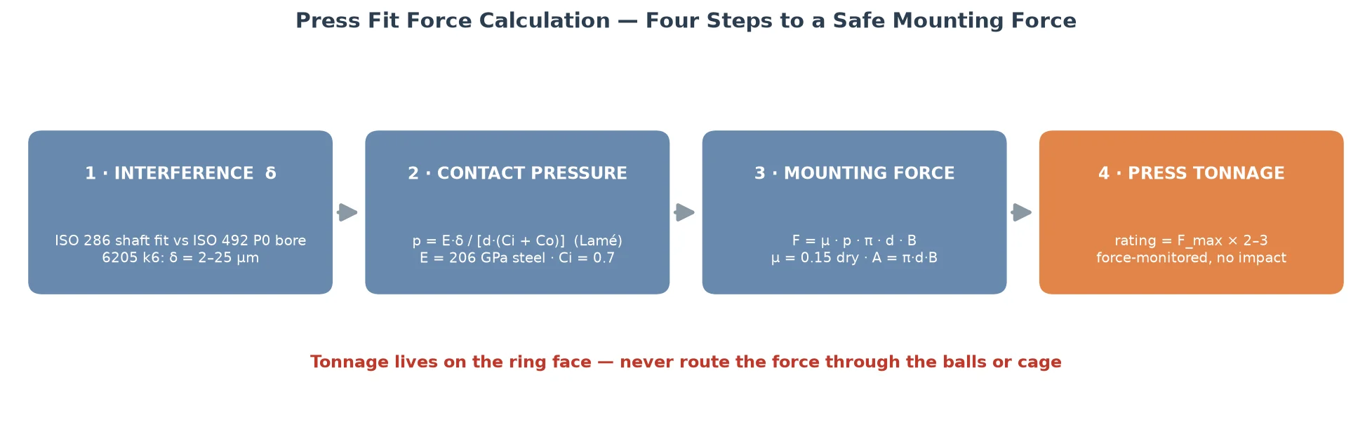
The press fit force calculation runs in four steps: interference first, then contact pressure, then force, then press tonnage.
Step 1 — Establish the Interference (δ)
The starting point of any press fit force calculation is the actual overlap between shaft and bore. Shaft tolerances follow ISO 286 (k6, m6, n6, p6 and so on), while bearing bores follow ISO 492: a P0-class inner ring runs 0 to −10 μm below nominal at a 25 mm bore. Because both the shaft and the bore carry tolerance bands, the interference itself is a range:
- Tightest fit — largest shaft (upper deviation) against smallest bore (lower deviation)
- Loosest fit — smallest shaft against largest bore
For a 6205 bearing (25 × 52 × 15 mm) on a k6 shaft, the +2/+15 μm shaft tolerance against a 0/−10 μm bore gives an interference range of 2 to 25 μm. Use the tightest value for tonnage selection. Also remember that surface roughness eats into the effective interference: a shaft ground to Ra 3.2 can lose 5–8 μm of effective overlap compared with Ra 0.8, which is why journals are usually specified at Ra 0.8 or better.
Step 2 — Calculate the Contact Pressure (Lamé)
The interference expands the inner ring elastically, and that expansion creates a radial contact pressure p. The Lamé thick-cylinder equation for a solid shaft inside a bearing ring is:
p = E × δ / [d × (Ci + Co)]
where E is the steel modulus (206 GPa), d is the fit diameter, and Ci and Co are stiffness factors of the two members. For a solid shaft, Ci = 0.7. The bearing ring is the subtle part: its effective outer diameter is the raceway pitch diameter, roughly (d + D)/2, not the bearing outer diameter. Treating the ring as an infinitely thick hub (Co = 1.3) overestimates the pressure by 40–70% — a very common error. For the 6205 example, the tightest 25 μm of interference produces about 60 MPa of contact pressure on the inner ring bore.
Step 3 — Add Friction and Contact Area (F = μ·p·A)
The mounting force is the friction over the whole contact area:
F = μ × p × A, where A = π × d × B
B is the bearing width (15 mm for a 6205), so the contact area is π × 25 × 15 ≈ 1,180 mm². The friction coefficient μ for ground steel on ground steel is roughly:
- 0.08 — light oil film during mounting
- 0.12 — pre-lubricated surfaces
- 0.15 — dry and clean; use this as the design value
- 0.20+ — rough or dry surfaces
For the 6205 on k6: F ≈ 0.15 × 60 MPa × 1,180 mm² ≈ 10.5 kN, or about 1.1 metric ton-force at the tightest fit. The loosest fit needs barely 0.1 ton-force — which is why the measured force varies so much from one bearing to the next.
Step 4 — Select the Press Tonnage
The calculated force is the minimum your press must deliver, and field conditions (actual interference, roughness, lubrication) can move it by ±50%. Industry practice is to rate the press at 2–3× the calculated maximum force:
- 6202 and 6205 (≈0.7–1.1 tf) — 3-tonne press, or induction heating
- 6208 and NU207 (≈1.5–1.8 tf) — 5-tonne press
- 6308 (≈2.6 tf) — 5–10 tonne press
- 22208 p6 (≈3.4 tf) — 10-tonne press
Always press with a force indicator or load cell, feed slowly, and stop immediately if the force climbs to more than 2–3× the calculated value. A steep climb means a burr, galling, a tapered or out-of-round shaft, or a mis-selected fit — investigate before continuing.
Press Fit Force Calculation Examples: Required Tonnage by Bearing Size
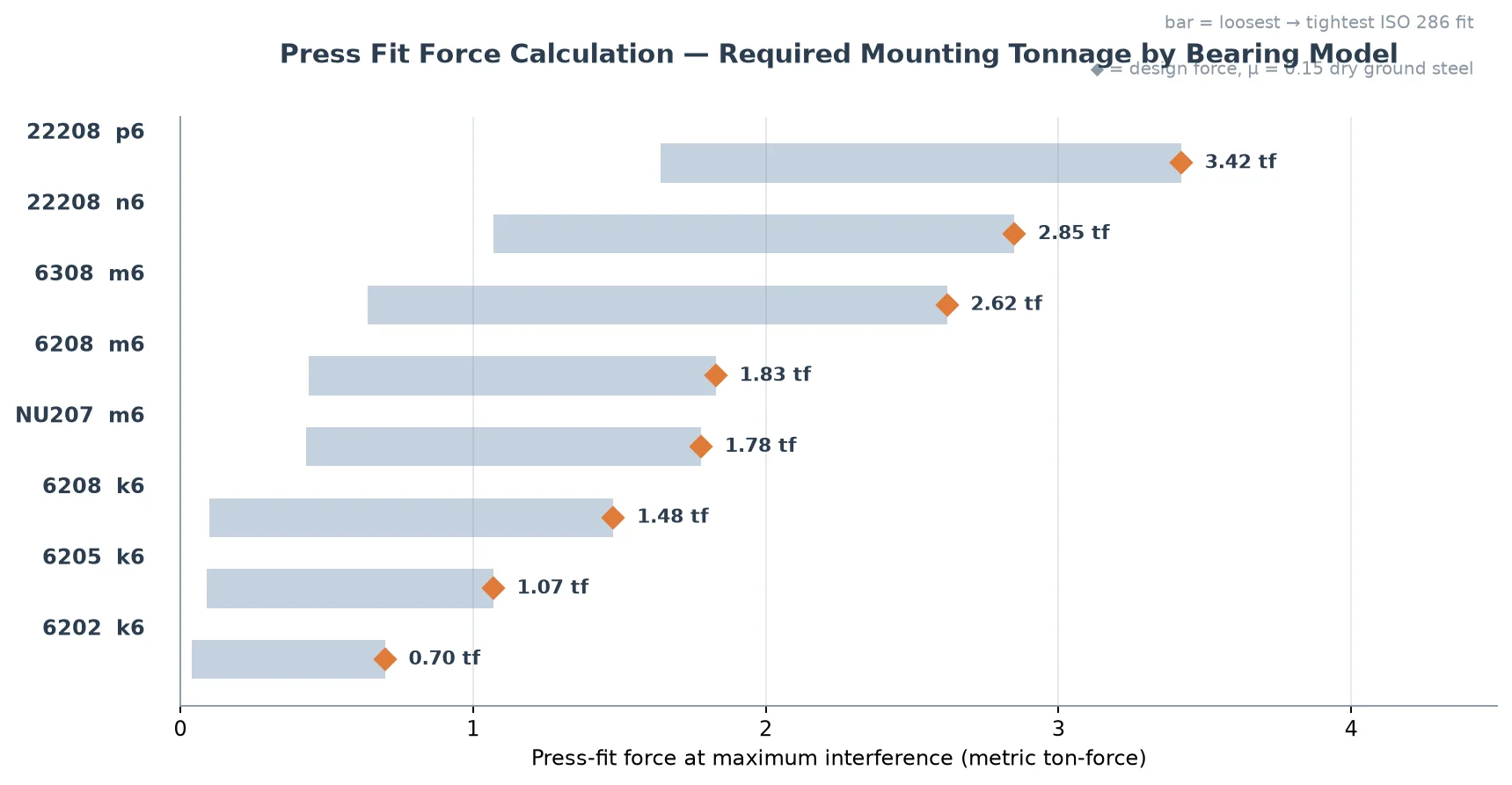
Table 1 summarizes the press fit force calculation for eight common shaft mounts, computed at μ = 0.15 with ISO 286 shaft fits against ISO 492 P0 bores. Values are for pressing the inner ring onto a solid shaft.
| Bearing | Size d×D×B (mm) | Shaft fit | Interference (μm) | Force range (kN) | Max tonnage (tf) |
|---|---|---|---|---|---|
| 6202 | 15 × 35 × 11 | k6 | 1–20 | 0.3–6.8 | 0.70 |
| 6205 | 25 × 52 × 15 | k6 | 2–25 | 0.8–10.5 | 1.07 |
| 6208 | 40 × 80 × 18 | k6 | 2–30 | 1.0–14.6 | 1.48 |
| 6208 | 40 × 80 × 18 | m6 | 9–37 | 4.4–18.0 | 1.83 |
| NU207 | 35 × 72 × 17 | m6 | 9–37 | 4.2–17.5 | 1.78 |
| 6308 | 40 × 90 × 23 | m6 | 9–37 | 6.2–25.7 | 2.62 |
| 22208 | 40 × 80 × 23 | n6 | 17–45 | 10.5–27.9 | 2.85 |
| 22208 | 40 × 80 × 23 | p6 | 26–54 | 16.1–33.5 | 3.42 |
Talos manufactures its deep groove ball bearings, cylindrical roller bearings and spherical roller bearings to the same ISO 286 and ISO 492 tolerance system used by SKF, NSK and FAG. The press fit force calculation above applies identically to a Talos 6205 2RS bearing as to any major brand’s — ISO-standard dimensions and load ratings, at direct-from-manufacturer pricing.
Why the Press Fit Force Calculation Protects the Cage and Races
The press fit force calculation does more than size the press — it exposes the single most common cause of mounting damage: the load path.
The load-path rule
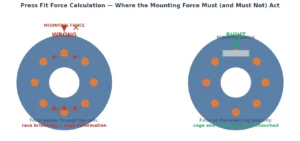
The force required to mount a bearing is large — one tonne or more for a mid-size bearing. That force is harmless as long as it enters the bearing through the ring that has the interference fit: the inner ring face when mounting onto a shaft, the outer ring face when pressing into a housing. A mounting sleeve distributes the load around the full circumference of that ring face.
The force must never pass through the rolling elements or the cage. Pressing on the outer ring while the inner ring is being forced onto a shaft sends the entire mounting force through the balls or rollers. At point contacts, that load crushes the raceways and bends the cage pockets.
The numbers behind the rule
Here is why the force is the problem, quantified. The 6205 press fit force calculation gives ≈10.5 kN at the tightest fit — but the static load rating C0r of a 6205 is only 7.8 kN. ISO 76 defines the static load rating as the load at which permanent deformation begins, roughly 4,200 MPa of contact stress. A mounting force routed through the balls therefore exceeds the bearing’s own static rating: permanent raceway dents at ball spacing — true brinelling — are the predictable result. The cage is even more vulnerable: a stamped steel cage deforms under a few hundred newtons of axial load. Neither the races nor the cage can survive even a fraction of the tonnage the press delivers, so the load path is everything.
Practical mounting rules
- Apply the force to the interference-fit ring face through a full-circumference sleeve (bore slightly larger than the shaft, outside diameter slightly smaller than the inner ring).
- Feed the press slowly and steadily; never use a hammer. Hardened rings (around 60 HRC) crack under impact loading.
- Light oil on the shaft before pressing reduces μ and the required force by roughly 20%.
- For heavy interference (m6 and above on larger sizes), heat the inner ring with an induction heater to 80–120 °C and the mounting force drops to nearly zero. Never exceed 120 °C, and keep sealed bearings below 100 °C.
- Monitor the force curve during the stroke: a sudden drop means the fit has slipped, a steep climb means a problem.
Our bearing mounting techniques guide covers the tooling, sleeves and procedures in full.
Common Misconceptions About Press Fit Force
- “Bigger tonnage is more dangerous.” Tonnage on the ring face is harmless even at 10 tf. Damage comes from the wrong load path, not the force magnitude.
- “A small bearing does not need a calculation.” A 6202 still needs up to 0.7 tf. If a bearing is being “persuaded” onto a shaft with a hammer, it is already damaged.
- “Pressing through the outer ring is fine as long as it is aligned.” No — any force through the balls brinells the raceways, aligned or not.
- “Rough shafts just mean more press force.” Roughness raises friction AND reduces effective interference, which causes creep in service. Grind journals to Ra 0.8 μm or better.
- “Heating to 150 °C speeds things up.” Above 120 °C the ring softens (tempering) and seals or cages can be destroyed.
- “The same force fits a housing as a shaft.” Housing press fits use different geometry and tolerances — a P7 housing bore, for example — so the calculation must be run for the outer ring separately.
Frequently Asked Questions
What is the press fit force calculation formula?
The formula is F = μ × p × A, where p is the Lamé contact pressure p = E × δ / [d × (Ci + Co)], A = π × d × B is the fit area, and μ is the friction coefficient (0.15 for dry ground steel). For a 6205 bearing on a k6 shaft this gives about 10.5 kN (1.1 tf) at maximum interference.
How accurate does a press fit force calculation need to be?
Accurate enough to size the press and to detect problems: ±30–50% is acceptable, because field friction and the actual interference vary that much. The real value is comparing the calculated force with the measured force during mounting — a reading 2–3× above calculation means stop and inspect before continuing.
Why is my measured press-in force higher than calculated?
Common causes are burrs or damaged shaft edges, surface roughness higher than expected, a tapered or out-of-round shaft, dry contact (no mounting oil), or a fit class tighter than specified (for example p6 instead of k6). Measure the shaft, clean the surfaces, and apply light oil before pressing.
Can I press a bearing on with a hammer?
No. Impact loads crack hardened rings and transmit the force through the rolling elements, denting the raceways and bending the cage. Use an arbor press or hydraulic press with the load applied to the inner ring face, or heat the inner ring with an induction heater.
When should I heat the bearing instead of pressing it?
When the fit is heavy (m6 and above on larger sizes), when the calculated force exceeds roughly 2 tf, or when the housing prevents access to the ring face. Induction heating to 80–120 °C expands the inner ring and reduces the mounting force to nearly zero. Never use a flame or oil bath, and keep sealed bearings below 100 °C. See SKF’s bearing mounting guidelines and dismounting guidelines for the full procedures.
Does the calculation change for the outer ring into a housing?
Yes. The geometry and the tolerances are different: the outer ring’s outside diameter runs 0/−13 μm at the 50–80 mm size step, and housing fits such as N7 can even be transition fits with a possible clearance. Run the same four steps with the outer-ring geometry and the housing bore tolerance before pressing into a housing.
Conclusion
Determining the required tonnage for a bearing press fit is a four-step calculation: establish the interference from ISO 286 and ISO 492, convert it to contact pressure with the Lamé equation, multiply by friction over the contact area, and rate the press at 2–3× the result. The press fit force calculation also doubles as a damage-prevention tool — it shows why the mounting force must act on the interference-fit ring face and never through the rolling elements or cage. Run the numbers before every press mounting, monitor the force while you press, and your bearings will reach service exactly as they left the factory.
Need bearings for your next press-fit assembly? Browse the Talos deep groove ball bearings range — ISO-standard dimensions, full load ratings, and direct-from-manufacturer pricing — or contact our engineering team for fit and mounting support.